Mosfet driver Solid State Relays on a DIN-rail
Microchip's 8-Bit I/O Expander with I²C Interface
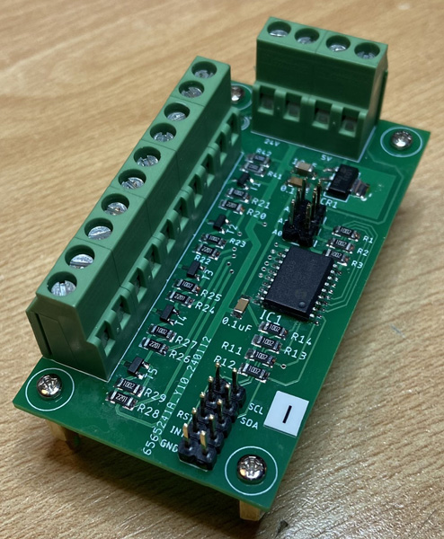
PCB (Printed Circuit Board):

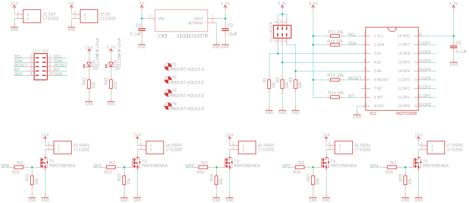
Click on the Schematic for a larger view:
MCP23008
Microchip's 8-Bit I/O Expander with I²C Interface
Features:
- 8-Bit Remote Bidirectional I/O Port
- High-Speed I2C Interface - 100 kHz, 400 kHz and 1.7 MHz
- Hardware Address Pins
- Configurable Interrupt Output Pin
- Configurable as active-high, active-low or open-drain
- Configurable Interrupt Source
- Interrupt-on-change from configured defaults or pin change
- Polarity Inversion Register to Configure the Polarity of the Input Port Data
- External Reset Input
- Low Standby Current: 1 µA (max.)
- Operating Voltage - 1.8V to 5.5V
- The device is supplied in 18-pin SOIC (300 mil)
LD1117S33TR
STMicroelectronics Adjustable and fixed low drop positive voltage regulator
Features:
- Fixed output voltage of 3.3 Volt
- Output current up to 800 mA (is a bit overkill ;-) )
- Low dropout voltage (1 V typ.)
- Internal current and thermal limit
- Supply voltage rejection: 75 dB (typ.)
- Only a very common 10 µF minimum capacitor is needed for stability
- The device is supplied in SOT-223
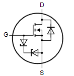
PMV230ENEA
NXP Semiconductors N-channel Trench MOSFET
Features:
- N-channel enhancement mode FET in a small SOT23 (TO-236AB) package
- Logic level compatible
- Very fast switching
- Trench MOSFET technology
- Drain-source voltage 60 V
- Gate-source voltage −20 V - +20 V
- Drain current 1.5 A
- ElectroStatic Discharge (ESD) protection > 2 kV HBM
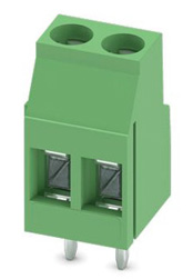
MKDS 3/2
PCB terminal block, Phoenix Contact
Features:
- No. of pos.: 2
- Type: PC terminal block, can be aligned
- Product line: COMBICON Terminals M
- Conductor cross section: 2.5 mm²
- Color: Green
- Pitch: 5 mm
- Connection method: Screw connection with tension sleeve
- Nominal current: 24 A
- Nominal voltage: 400 V
- Connection direction: 0 °
- Order No.: 1711026
Board pinout
-
Power pins
- Positive Power
- 5 Volt:
- goes to 3.3 Volt voltage regulator
- Raspberry Pi
- 24 Volt, goes to the relays
- 5 Volt:
- GND - This is common ground for power and logic.
- 5 Volt
- 24 Volt
- I²C
- SCL - this is the I²C clock pin
- SDA - this is the I²C data pin
- RST - This is the reset pin. Connect this pin to ground to reset the board.
- INT - The MCP23008 has interrupt capabilities. If you want to have a quick way of telling if any of the GPIO's changed.
I²C Data pins
Reset and Interrupt pins
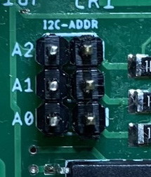
Check MCP23008 address
Type into the cli:$ sudo i2cdetect -y 1
There should be a HEX number into the matrix. Default is 0x20. You can set the I²C address by tying the ADDR pins to power or ground, for up to 8 unique addresses.
This board/chip uses I²C 7-bit address between 0x20-0x27, selectable with jumpers.
The table below shows all possible addresses, and whether the pin(s) should be High (closed) or Low (open).
| Address | A0 | A1 | A2 |
|---|---|---|---|
| 0x20 (default) | L | L | L |
| 0x21 | H | L | L |
| 0x22 | L | H | L |
| 0x23 | H | H | L |
| 0x24 | L | L | H |
| 0x25 | H | L | H |
| 0x26 | L | H | H |
| 0x27 | H | H | H |
On the top of the board are three address jumpers, labeled A0, A1, and A2:
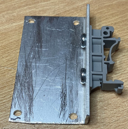
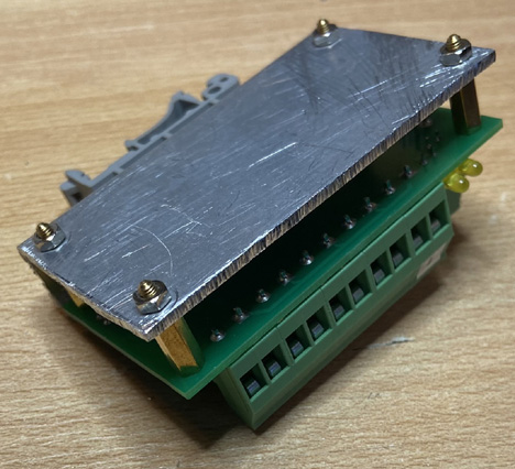
PCB and aluminium L-profile with a DIN Railadapter