Adafruit HUZZAH32
Adafruits ESP32 breakout board

Specs
- 240 MHz dual core Tensilica LX6 microcontroller with 600 DMIPS
- Integrated 520 KB SRAM
- Integrated 802.11b/g/n HT40 Wi-Fi transceiver, baseband, stack and LWIP
- Integrated dual mode Bluetooth (classic and BLE)
- 4 MByte flash include in the WROOM32 module
- On-board PCB antenna
- Ultra-low noise analog amplifier
- Hall sensor
- 10x capacitive touch interface
- 32 kHz crystal oscillator
- 3 x UARTs (only two are configured by default in the Feather Arduino IDE support, one UART is used for bootloading/debug)
- 3 x SPI (only one is configured by default in the Feather Arduino IDE support)
- 2 x I2C (only one is configured by default in the Feather Arduino IDE support)
- 12 x ADC input channels
- 2 x I2S Audio
- 2 x DAC
- PWM/timer input/output available on every GPIO pin
- OpenOCD debug interface with 32 kB TRAX buffer
- SDIO master/slave 50 MHz
- SD-card interface support
Pinouts
Power pins

- GND - this is the common ground for all power and logic
- BAT - this is the positive voltage to/from the JST jack on the back as well as input into the 3.3V regulator
- V+ - this is the positive voltage from the USB-to-Serial converter if one is plugged into the 6-pin header
- 3V - this is the output from the 3.3V regulator. The regulator can supply 500mA peak but half of that is drawn by the ESP32, and it's a fairly power-hungry chip. So if you need a ton of power for stuff like LEDs, motors, etc. Use the USB or BAT pins, and an additional regulator
Serial pins

RX and TX are the main serial pins, and are connected to the USB/Serial converter. These are for use to program/bootload or debug the ESP32. They shouldn't be connected to any other hardware since the bootloader uses these pins only!
Logic pins
All logic is 3.3V!!
This is the general purpose I/O pin set for the microcontroller.
There are tons of GPIO and analog inputs available to you for connecting LEDs, buttons, switches, sensors, etc.. Here's the remaining pins available. Note that SPI/I2C/UART can be on any pins but Adafruit mark out the ones Adafruit set up in our Arduino definition which is probably what you want. Likewise for the analog pin names.
- IO0 - Used primarily for bootloader detect. Hold low while resetting to enter the bootloader. This is also connected to a small tactile button on the board
- IO2 - This is GPIO #2
- IO4 - This is GPIO #4 and also an analog input A5 on ADC #2
- IO5 - This is GPIO #5 and also SPI SCK
- IO12 - This is GPIO #12 and also an analog input A11 on ADC #2. This pin has a pull-down resistor built into it, we recommend using it as an output only, or making sure that the pull-down is not affected during boot
- IO13 - This is GPIO #13 and also an analog input A12 on ADC #2. It's also connected to the red LED next to the USB port
- IO14 - This is GPIO #14 and also an analog input A6 on ADC #2
- IO15 - This is GPIO #15 and also an analog input A8 on ADC #2
- IO16 - This is GPIO #16 and also Serial1 RX
- IO17 - This is GPIO #17 and also Serial1 TX
- IO18 - This is GPIO #18 and also SPI MOSI
- IO19 - This is GPIO #19 and also SPI MISO
- IO21 - This is GPIO #21
- IO22 - This is GPIO #22 and also I2C SDA
- IO23 - This is GPIO #23 and also I2C SCL
- IO25 - This is GPIO #26 and an analog input A1 on ADC #2 and also an analog output DAC1
- IO26 - This is GPIO #26 and an analog input A0 on ADC #2 and also an analog output DAC2
- IO27 - This is GPIO #27 and also an analog input A10 on ADC #2
- IO32 - This is GPIO #32 and also an analog input A7 on ADC #1. It can also be used to connect a 32 KHz crystal
- IO33 - This is GPIO #33 and also an analog input A9 on ADC #1. It can also be used to connect a 32 KHz crystal
- I34 - This is GPI #34 and also an analog input A2. Note it is not an output-capable pin! It uses ADC #1
- I35 - This is GPI #35 and also an analog input A13. Note it is not an output-capable pin! It uses ADC #1
- I36 - This is GPI #36 and also an analog input A4. Note it is not an output-capable pin! It uses ADC #1
- I39 - This is GPI #39 and also an analog input A3. Note it is not an output-capable pin! It uses ADC #1
Special pins
- A2 / I34 - this pin is an input only! You can use it as an analog input so we suggest keeping it for that purpose
- A3 / I39 - this pin is an input only! You can use it as an analog input so we suggest keeping it for that purpose
- IO12 - this pin has an internal pulldown, and is used for booting up. We recommend not using it or if you do use it, as an output only so that nothing interferes with the pulldown when the board resets
- A13 / I35 - this pin is not exposed, it is used only for measuring the voltage on the battery. The voltage is divided by 2 so be sure to double it once you've done the analog reading
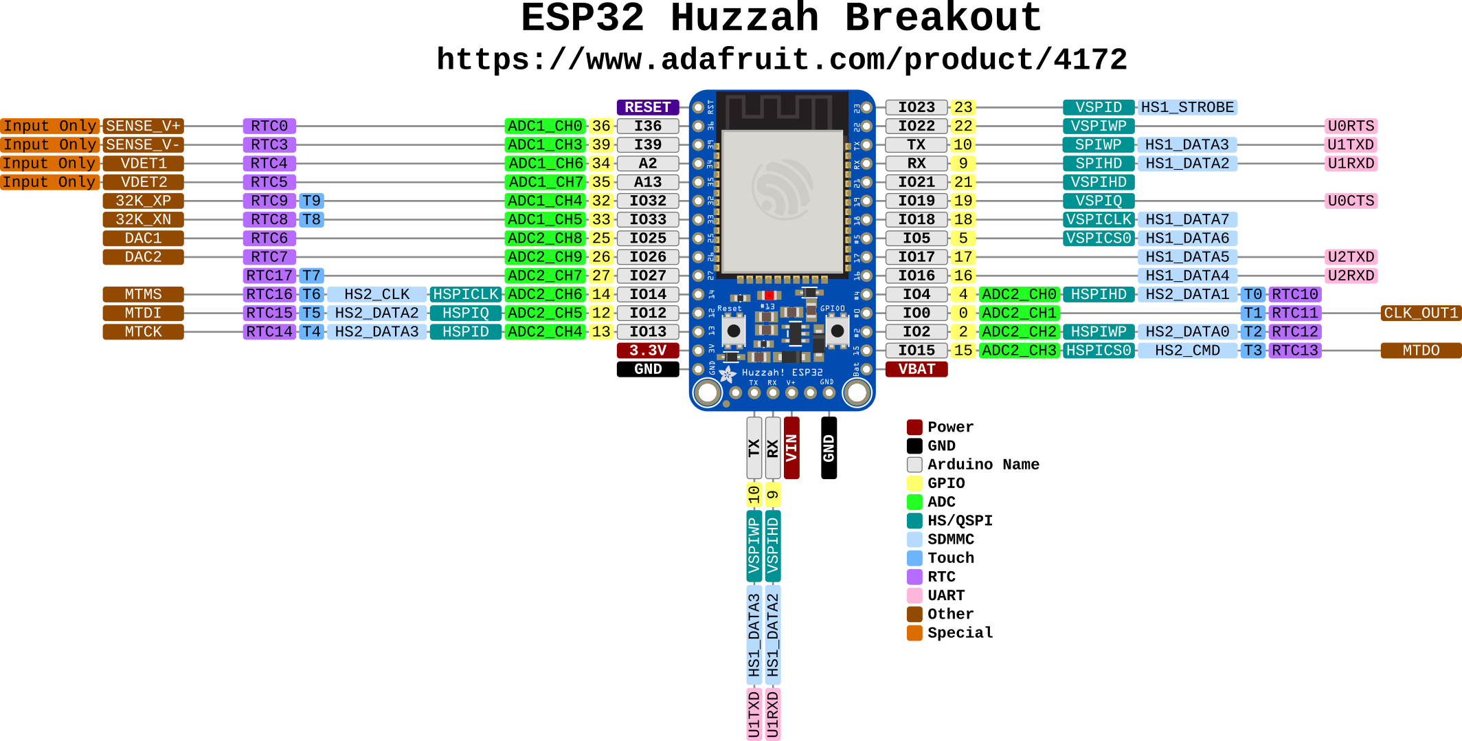
Pinout
Click image for original size.