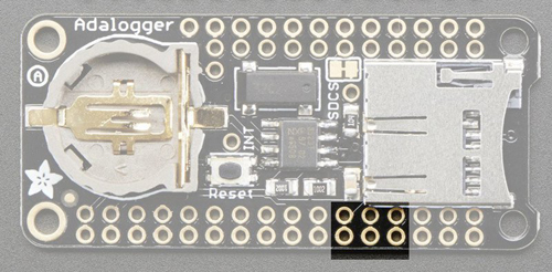
Adafruit Adalogger FeatherWing
RTC + SD-card Add-on, for all Feather boards and more!
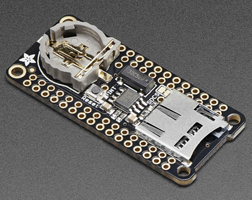
This FeatherWing will make it real easy to add datalogging to any of the existing Feathers. You get both an I²C real time clock (PCF8523) with 32KHz crystal and battery backup, and a microSD socket that connects to the SPI port pins (+ extra pin for CS). If you're not using the RTC part of the FeatherWing, a battery is not required.
Adafruit has tested it and the Adalogger works great with any of the Feathers, based on:
- ATmega32u4
- ATmega328P
- ATSAMD21
- ATSAMD51
- nRF52
- Teensy
- ESP32
- ESP8266
Pinout
Even though every pin from the Feather isdoubled upwith an inner header not all of the pins are actually used!
Power pins
On the bottom row, the 3.3V (second from left) and GND (fourth from left) pin are used to power the SD card and RTC (to take a load off the coin cell battery when main power is available).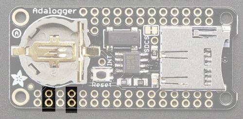
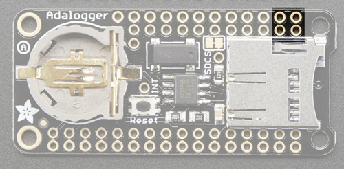
RTC & I²C pins
In the top right, SDA (rightmost) and SCL (to the left of SDA) are used to talk to the RTC chip.
- SCL - I²C clock pin, connect to your microcontrollers I²C clock line. This pin has a 10K pullup resistor to 3.3V
- SDA - I²C data pin, connect to your microcontrollers I²C data line. This pin has a 10K pullup resistor to 3.3V
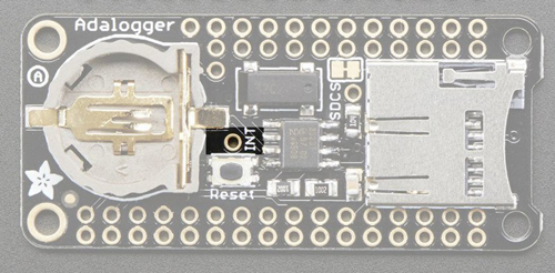
There's also a breakout for INT which is the output pin from the RTC. It can be used as an interrupt output or it could also be used to generate a square wave.
Note that this pin is open drain - you must enable the internal pullup on whatever digital pin it is connected to!
SD & SPI pins
Starting from the left you've got:
- SPI Clock (SCK) - output from feather to wing
- SPI Master Out Slave In (MOSI) - output from feather to wing
- SPI Master In Slave Out (MISO) - input from wing to feather
SDCS Line
The SDCS pin is the chip select line.- On ESP8266, the SD CS pin is on GPIO 15
- On ESP32 it's GPIO 33
- On WICED it's GPIO PB5
- On the nRF52832 it's GPIO 11
- On Atmel M0, M4, 328p or 32u4 it's on GPIO 10
- On Teensy 3.x it's on GPIO 10
