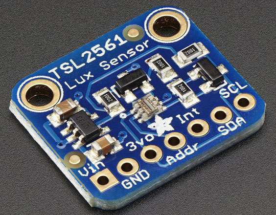
TSL2561 Lux sensor on Adafruit breakout board
TAOS Inc. I²C lux sensor
Some quick specs
- Precisely Measures Illuminance in Diverse Lighting Conditions IR & visible light
- Sensor contains two channels; visible light and IR and IR only. Both channels can be used simultaneously
- Voltage range 2.7 - 3.6V
- Onboard voltage regulator (3.3V) and levelshifters
- Power typical 0.5mA and less than 15µA when in powerdown mode
- Dynamic range (Lux): 0.1 to 40.000 Lux
Breakout board pinout
Power pins- Vin - this is the power pin. Since the sensor chip uses 3 VDC, we have included a voltage regulator on board that will take 3-5VDC and safely convert it down. To power the board, give it the same power as the logic level of your microcontroller - e.g. for a 5V micro like Arduino, use 5V
- 3Vo - this is the 3.3V output from the voltage regulator, you can grab up to 100mA from this if you like
- GND - common ground for power and logic
I²C Logic pins
- SCL - this is the I2C clock pin, connect to your microcontrollers I2C clock line
- SDA - this is the I2C data pin, connect to your microcontrollers I2C data line
Extra pins
- ADDR - The ADDR pin can be used if you have an i2c address conflict, to change the address, see I2C Addressing
- INT - The INT pin is an ouput from the sensor used when you have the sensor configured to signal when the light level has changed. We don't have that code written in this tutorial so you don't have to use it. If you do end up using it, use a 10K-100K pullup from INT to 3.3V (Vcc)
I²C Addressing
The TSL2561 has three I2C addresses 0x29, 0x39 and 0x49.0x29 connect ADDR to Ground
0x39 leave ADDR unconnected, so this is default
0x49 connect ADDR to Vcc
Python
External addresses to Adafruit:Python & CircuitPython
Python Docs (Adafruit TSL2561 Python Library)
Schematic
