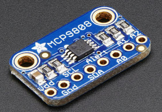
MCP9808 Temperature Sensor on Adafruit breakout board
Microchip's I²C High Accuracy Digital Temperature Sensor
Some quick specs
- Cheap ($4.95 for complete breakout board)
- Simple I²C control
- Up to eight MCP9808 on a single I²C bus with adjustable address pins (see I²C Addressing)
- 0.25°C typical precision over -40°C to 125°C range (0.5°C guaranteed max from -20°C to 100°C)
- 0.0625°C resolution
- 2.7V to 5.5V power and logic voltage range (3.3V typical)
- Operating Current: 200 µA (typical)
- Uses any I²C address from 0x18 thru 0x1F
- Datasheet
Breakout board pinout
-
Power pins
- Vdd - This is the positive power and logic level pin. It can be 2.7-5.5VDC, so fine for use with 3 or 5V logic. Power Vdd with whatever logic level you plan to use on the i²c lines
- GND - this is the ground power and logic reference pin
- SCL - this is the I²C clock pin. There's a 10K pull-up already on the board, so connect this directly to the i²c master clock pin on your microcontroller
- SDA - this is the I²C data pin. There's a 10K pull-up already on the board, so connect this directly to the i²c master data pin on your microcontroller
- Alert - This is the interrupt/alert pin from the MCP9808. The chip has some capability to 'alert' you if the chip temperature goes above or below a set amount. This output can trigger to let you know. It is open collector so you need to use a pull-up resistor if you want to read signal from this pin
- A0, A1, A2 - These are the address select pins. Since you can only have one device with a given address on an i²c bus, there must be a way to adjust the address if you want to put more than one MCP9808 on a shared i²c bus. The A0/A1/A2 pins correspond to the Least Significant Bits (LSBs) of the address bits of the i²c address. There are pull-down resistors on the board so connect them to Vdd to set the bits to '1'. They are read on power up, so de-power and re-power to reset the address
I²C Data pins
Optional pins
I²C Addressing
The default address is 0x18, no address select pin is connected to Vdd.The address can be calculated by 'adding' the A0/A1/A2 to the base of 0x18
- A0 sets the lowest bit with a value of 1
- A1 sets the middle bit with a value of 2
- A2 sets the high bit with a value of 4
| Connect pins to Vdd to set the bits to '1' | |||
|---|---|---|---|
| HEX / Decimal | A0 (1) | A1 (2) | A2 (4) |
| 0x18 (24) | |||
| 0x19 (25) | 1 | ||
| 0x1A (26) | 1 | ||
| 0x1B (27) | 1 | 1 | |
| 0x1C (28) | 1 | ||
| 0x1D (29) | 1 | 1 | |
| 0x1E (30) | 1 | 1 | |
| 0x1F (31) | 1 | 1 | 1 |
Python
External addresses to Adafruit:Python & CircuitPython
Python Docs (Adafruit MCP9808 Python Library)
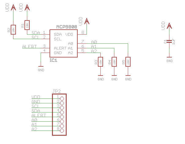
Schematic