INA219 High Side DC Current Sensor
Texas Instruments zero-drift, bi-directional current/power monitor with I²C interface.
Some quick specs
- 0.1 ohm 1% 2W current sense resistor
- Up to +26V DC target voltage
- Up to ±3.2A current measurement, with ±0.8mA resolution
- Datasheet
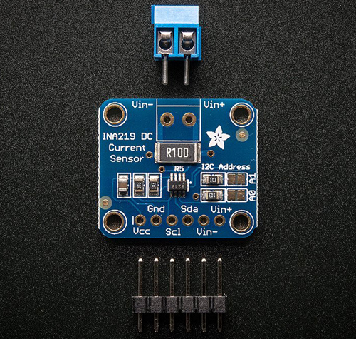
Breakout board pinout
Power pins- Vcc - This is the positive power and logic level pin. It can be 3V to 5.5V DC, so fine for use with 3 or 5V logic. Power VDD with whatever logic level you plan to use on the i2c lines
- Gnd - this is the ground power and logic reference pin
- SCL - I2C clock pin. There's a 10K pull-up already on the board, so connect this directly to the i2c master clock pin on your microcontroller
- SDA - I2C data pin. There's a 10K pull-up already on the board, so connect this directly to the i2c master data pin on your microcontroller
- V+ Connect to the positive terminal of the power supply for the circuit under test.
- V- Connect to the positive terminal or lead of the load. This puts the sense resistor in-line with the circuit.
- Finally, connect a wire from the negative terminal of the power supply to GND. This allows the sensor to measure the load voltage as well as the load current.
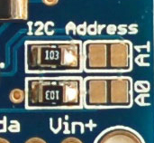
I²C Addressing
The INA219 has four I2C addresses selectable with solder jumpers.
- Address 0x40 default (no jumpers required)
- Address 0x41 (bridge A0 with solder)
- Address 0x44 (bridge A1 with solder)
- Address 0x45 (bridge A0 & A1 with solder)
Python
External addresses to Adafruit:CircuitPython
How to connect
A detailed tutorial that will do all the gain, range and math for you!
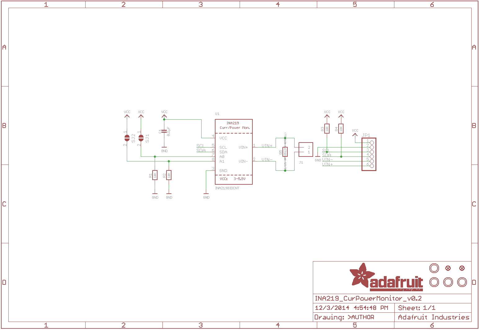
Schematic