Differential I²C Breakout
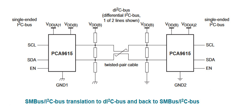
Differential I²C with NXP's PCA9615, to extend the physical length of the I²C bus.

I²C is never made for long distances. It is used on printed circuit boards (PCB) to connect different parts together. So that is only a couple of inches/centimeter at best. So what to do if you want to connect an I²C device further away? You use a differential I²C bus. Sparkfun's breakout board is very nice, because you can power your I²C devices of it as well. You can for example putting a temperature sensor outdoors and your Raspberry/microcontroller safe and sound indoors.
Some quick specs
- Uses the PCA9615 buffer
- I²C Supply voltage range 2.3-5.5V
- Differential Supply voltage range 3-5.5V
- Draws 16µA of current
- Extends I²C bus up to 100 feet (~ 30 meter)
- Data rate up to 400kHz
- 2x Qwiic Connectors
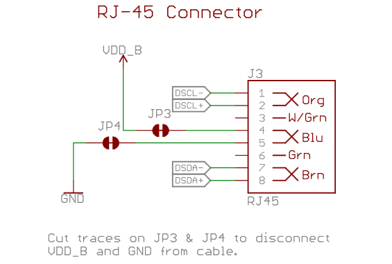
- RJ45 Connector
Breakout board pinout

- GND - Ground
- VDDA - 2.3VDC to 5.5VDC. I2C-bus side power supply
- VDDB - 3.0VDC to 5.5VDC. Differential side power supply. If jumper
VDD A-B
is not shorted, then VDDB will need to be powered for the differential I2C bus to operate - SDA - I²C data signal
- SCL - I²C clock signal
- EN (optional) - PCA9615 enable (active high, internally pulled up). This is used to disable the bus buffer, and is useful for fault finding, power-up sequencing, or reconfiguration of a large bus system by isolating sections not needed at all times.
- GND - Ground
- VDDA - 2.3VDC to 5.5VDC. I2C-bus side power supply. If
VDD A-B
is not shorted, VDDB will need to powered separately for the differential I2C bus to operate - SDA - I²C data signal
- SCL - I²C clock signal
- GND - Black
- 3V3 - Red
- SDA - Blue
- SCL - Yellow
Use CAT-5e cables made according to the 568B standard.
VDDA vs VDDB
To power the board, VDDA must be present and be the same logic voltage as the SDA/SCL lines, while VDDB is used to power the differential I2C bus. By default, the jumper labeled VDD A-B
is closed, which connects the VDDA rail to the VDDB rail. By cutting the jumper you can separate the two rails which would allow for one rail to operate at 3.3V while the other can operate at 5V.

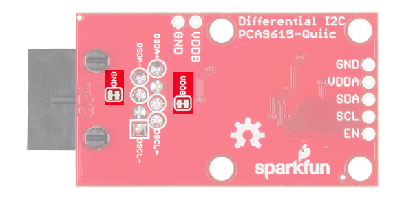
VDDB and Ground Jumpers
If the number of sensors connected on the other side of the extended I2C bus is minimal, you can power them over the Ethernet cable. However, if there are numerous sensors connected, it is advised that both ends be powered separately. To isolate the power supplies at both ends of the Ethernet cable, use a sharp blade to cut the small traces betweens the pads of the jumpers labeled VDDB
and GND
. VDDB will still be present on each board, but the Ethernet cable will not carry any current to power a device at the other end of the cable.
Differential Signals
From the bottom of the board, we can see which pins the RJ-45 connector uses for the differential signaling. The board has been designed to use a standard Ethernet cable. If a custom cable is made, make sure to connect a twisted pair for pins 1 and 2 (DSCL-, DSCL+) and pins 7 and 8 (DSDA-, DSDA+)
I²C Pull-Up Resistors
As with most SparkFun I2C products, there is a jumper for the pull-up resistors on the I2C bus. If multiple sensors are connected to the bus with the pull-up resistors enabled, the parallel equivalent resistance will create too strong of a pull-up for the bus to operate correctly. As a general rule of thumb, disable all but one pair of pull-up resistors if multiple devices are connected to the bus.
Info